Electrode Current Drivers
Electrode Current Drivers#
Design a PTAT current sink driver with largest output impedance possible. Assume \(I_{source}\) is an ideal current source.
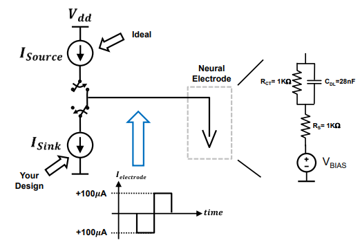
Fig. 3 Top Level View#
The output resistance is seen as the cascode output resistance multiplied by the gain. The cascode amplifier and PTAT current source are investigated to determine how much gain needs to be designed.
\[\begin{split}
\begin{align*}
|A_V| &= G_m R_{out} \\[0.25em]
|A_V| &\approx g_{m1} \left[r_{02}+(A_1 + 1)g_{m2} r_{02} + r_{01}\right] \\[0.25em]
|A_V| &\approx g_{m1} \left[g_{m2} r_{01} r_{02}A_1\right]
\end{align*}
\end{split}\]
The ideal gain for a differential telescopic amp is
\[ A_v = g_{m1} (g_{m2} r_{04} r_{05} || g_{m6} r_{06} r_{07}).\]
…