Low Noise Amplifier
Low Noise Amplifier#
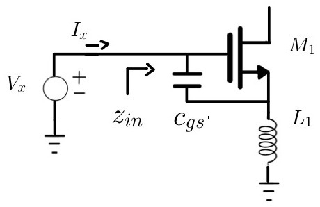
Fig. 5 Inductive Degeneration#
Looking at the gate of the LNA, a test voltage is applied to find the input impedance.
Exclude the additional capacitance between the gate and source.
At resonance, the third term provides a real impedance that is matched to the source impedance \(R_s\) (\(50 \Omega\)). This is simplified given \(\omega_T \approx \dfrac{g_m}{C_{gs}}\).
\(\omega_T\) is determined by the gain necessary for your application.
As a designer, there are two issues with this value.
It cannot be implemented with most PDKs. Inductors on chip are planar (2D) and have limited range.
It doesn’t resonant well due to small capacitance \(C_{gs}\).
However, it is possible to add a small capacitor in parallel with \(C_{gs}\) such that \(C_{tot} = C_{gs} + C_{gs'}\).
The input impedance is now
Remaining Steps
Pick minimum value for \(L_1\) that exists in the PDK and has sufficient \(Q\). Then, perform ac small signal analysis to find input impedance and slowly increase \(C_{gs'}\).