Coupled Resonators
Contents
Coupled Resonators#
Topics#
Mutual inductance of two shielded-loop resonators
Effects of distance and alignment on mutual inductance
Critical coupling distance
Full-wave bridge rectifiers
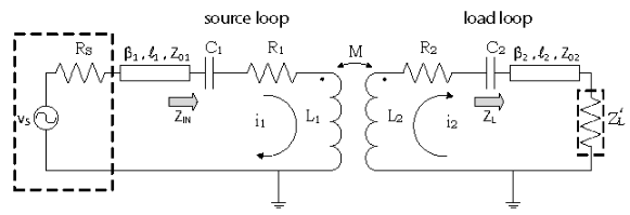
Fig. 39 Coupled Shielded-Loop Resonator with Load#
Calculating Mutual Inductance#
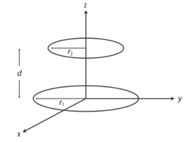
Fig. 40 Mutual Inductance for Axially Aligned Coupled Loops#
where \(K(k)\) is the complete elliptical integral with radius \(r_1\) and \(E(k)\) is the complete elliptical integral with radius \(r_2\).
Input Impedance of Coupled Shielded-Loop Resonators#
At resonance, the input impedance to the coupled shielded-loop simplifies to
Feedline Effects#
The load impedance \(Z_L\) is designed to the characteristic impedance \(Z_0\) of the transmission line to eliminate feedline effect and reduce the circuit model.
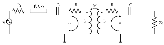
Fig. 41 Impedance Simplification#
Weak, Critical and Strong Coupling#
Isolated loop resonance occurs when
Coupled loop resonance also occurs when
Solving this quadratic equation results in multiple solutions depending on the mutual inductance as a function of distance.
Strong coupling
Odd mode solution: frequency is slightly less than \(\omega_0\) and the currents in the coupled loops are 180° out-of-phase
Even mode solution: frequency is slightly greater than \(\omega_0\) and the currents in the coupled loops are in-phase
Resonant frequency: \(\omega_0\) the current in the load loop leads that of the source loop by approximately 90°
Critical coupling
The even and odd mode frequencies merge into the resonant frequency \(\omega_0\)
Weak coupling
In weak coupling, there is only one resonant frequency \(\omega_0\)
Power Transfer#
The power transfer efficiency of a wireless power transfer system is the ratio of power delivered to the load \(P_L\) and the power available from the source \(P_A\).
\(Z_S\) characteristic impedance of the voltage source where \(Re\{Z_S\} = R_S\)
\(V_S\) peak voltage of the source
\(P_A\) power available from the source if the source impedance is terminated in an impedance equal to its complex conjugate
For a system operating at critical or weak coupling, the power transfer efficiency is
For a system operating at strong coupling (even or odd), the power transfer efficiency is
For matched source and load impedances (\(50 \Omega\)), the power transfer efficiency is
Voltage Rectification#
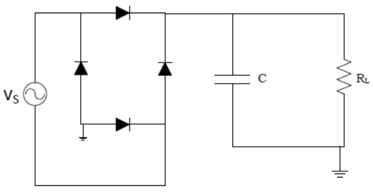
Fig. 42 Full Wave Bridge Rectifier#
In this circuit, the negative cycle of the input AC signal is not blocked. Instead it is converted to a positive value for the RC filter to “smooth”
Given metrics since vector analyzer has maximum output power of 0 dBm.
Input Return Loss (dB) |
Input Impedance (\(\Omega\)) |
|
|---|---|---|
Rectifier at \(\omega = \omega_0\) |
\(-0.486\) |
\(9.221 - j119.4\) |
Measurements#
5 cm loop and \(\omega = \omega_0\)
Distance (cm) |
\(\Gamma_{in}' (mU)\) |
\(S_{21} (dB)\) |
\(R_{in}\) |
\(M (calc.)\) |
\(\eta (calc.)\) |
|---|---|---|---|---|---|
2 |
|||||
4 |
|||||
6 |
|||||
8 |
|||||
10 |
|||||
12 |
|||||
14 |
|||||
16 |
9 cm loop and \(\omega = \omega_0\)
Distance (cm) |
\(\Gamma_{in}' (mU)\) |
\(S_{21} (dB)\) |
\(R_{in}\) |
\(M (calc.)\) |
\(\eta (calc.)\) |
|---|---|---|---|---|---|
2 |
|||||
4 |
|||||
6 |
|||||
8 |
|||||
10 |
|||||
12 |
|||||
14 |
|||||
16 |